VXLAN Data Plane – Cisco Network Virtualization
VXLAN Data Plane
VXLAN uses stateless tunnels between VTEPs to transmit traffic of the overlay Layer 2 network through the Layer 3 transport network. Let’s discuss a few terms before we look at the actual packet walk for the VXLAN data plane:
- Layer 2 VNI: An EVPN VXLAN tenant can have multiple Layer 2 networks, each with a corresponding VNI. These Layer 2 networks are bridge domains in the overlay network. The VNIs associated with them are often referred to as Layer 2 (L2) VNIs. A VTEP can have all or a subset of the Layer 2 VNIs in a VXLAN EVPN.
- Layer 3 VNI: Each tenant VRF instance is mapped to a unique Layer 3 VNI in the network. This mapping needs to be consistent on all the VTEPs in network. All inter-VXLAN routed traffic is encapsulated with the Layer 3 VNI in the VXLAN header and provides the VRF context for the receiving VTEP. The receiving VTEP uses this VNI to determine the VRF context in which the inner IP packet needs to be forwarded. This VNI also provides the basis for enforcing Layer 3 segmentation in the data plane.
- VTEP router MAC address: Each VTEP has a unique system MAC address that other VTEPs can use for inter-VNI routing. This MAC address is referred to as the router MAC address. The router MAC address is used as the inner destination MAC address for the routed VXLAN packet. As shown in Figure 7-16, when a packet is sent from VNI A to VNI B, the ingress VTEP routes the packet to the Layer 3 VNI. It rewrites the inner destination MAC address to the egress VTEP’s router MAC address and encodes the Layer 3 VNI in the VXLAN header. After the egress VTEP receives the encapsulated VXLAN packet, it first decapsulates the packet by removing the VXLAN header. Then it looks at the inner packet header. Because the destination MAC address in the inner packet header is its own MAC address, it performs a Layer 3 routing lookup. The Layer 3 VNI in the VXLAN header provides the VRF context in which this routing lookup is performed.
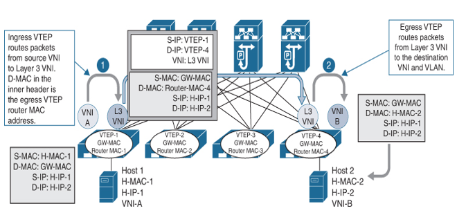
Figure 7-16 VXLAN Routing
When an EVPN VTEP performs forwarding lookup and VXLAN encapsulation for the packets it receives from its local end hosts, it uses either a Layer 2 VNI or the Layer 3 VNI in the VXLAN header, depending on whether the packets need to be bridged or routed. If the destination MAC address in the original packet header does not belong to the local VTEP, the local VTEP performs a Layer 2 lookup and bridges the packet to the destination end host located in the same Layer 2 VNI as the source host. The local VTEP embeds this Layer 2 VNI in the VXLAN header. In this case, both the source and destination hosts are in the same Layer 2 broadcast domain. If the destination MAC address belongs to the local VTEP switch (that is, if the local VTEP is the IP gateway for the source host, and the source and destination hosts are in different IP subnets), the packet will be routed by the local VTEP. In this case, it performs Layer 3 routing lookup. It then encapsulates the packets with the Layer 3 VNI in the VXLAN header and rewrites the inner destination MAC address to the remote VTEP’s router MAC address. Upon receipt of the encapsulated VXLAN packet, the remote VTEP performs another routing lookup based on the inner IP header because the inner destination MAC address in the received packet belongs to the remote VTEP itself.
The destination VTEP address in the outer IP header of a VXLAN packet identifies the location of the destination host in the underlay network. VXLAN packets are routed toward the egress VTEP through the underlay network based on the outer destination IP address. After the packet arrives at the egress VTEP, the VNI in the VXLAN header is examined to determine the VLAN in which the packet should be bridged or the tenant VRF instance to which it should be routed. In the latter case, the VXLAN header is encoded with a Layer 3 VNI. A Layer 3 VNI is associated with a tenant VRF routing instance, so the egress VTEP can directly map the routed VXLAN packets to the appropriate tenant routing instance. This approach makes multitenancy easier to support for both Layer 2 and Layer 3 segmentation. The following two VXLAN data plane packet walk examples illustrate the VXLAN bridging and routing concept.