Overlay Network Protocols – Cisco Network Virtualization
Overlay Network Protocols
Modern virtualized data center fabrics must meet certain requirements to accelerate application deployment and support DevOps needs. For example, fabrics need to support scaling of forwarding tables, scaling of network segments, Layer 2 segment extension, virtual device mobility, forwarding path optimization, and virtualized networks for multitenant support on shared physical infrastructure. Overlay network protocols such as NVGRE, Cisco OTV, VXLAN, and so on help to achieve these requirements. Before we discuss various overlay network protocols, let’s first make sure you understand the concepts of underlay and overlay.
An underlay network is the physical infrastructure above which an overlay network is built. It is the underlying network responsible for the delivery of packets across networks. In data center environments, the role of the physical underlay network is to provide unicast IP connectivity from any physical device (server, storage device, router, or switch) to any other physical device. Underlay networks are less scalable due to technology limitations.
Network overlays are virtual networks of interconnected nodes that share an underlying physical network, allowing deployment of applications that require specific network topologies without the need to modify the underlying network. Multiple overlay networks can coexist at the same time.
Figure 7-1 illustrates underlay and overlay network concepts.
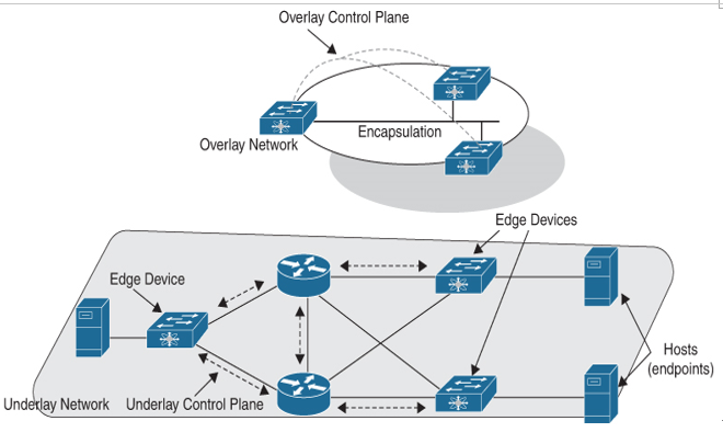
Figure 7-1 Underlay and Overlay Networks
There are two types of overlay networks:
- Layer 2 overlays: Layer 2 overlays emulate a LAN segment and transport both IP and non-IP packets, and forwarding is based on Ethernet frame headers. Mobility is restricted to a single subnet (that is, a single L2 domain). Since it’s a single L2 domain, Layer 2 floods are not uncommon. Layer 2 overlays are useful in emulating physical topologies.
- Layer 3 overlays: Layer 3 overlays abstract IP-based connectivity and transport IP packets. They provide full mobility regardless of subnets. Flooding is contained to network-related failures. Layer 3 overlays are useful in abstracting connectivity and policy.
Figure 7-2 illustrates Layer 2 and Layer 3 overlays.
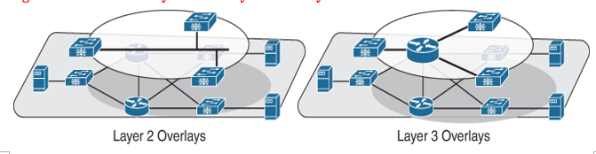
Figure 7-2 Layer 2 and Layer 3 Overlays
Depending on the types of overlay edge devices (that is, where the virtualized network is terminated), overlays are classified into three categories.
- Network-based overlays: In network-based overlays, edge routers/switches act as endpoints. Encapsulation and forwarding are performed at the edge router/switch. Tunneling is initiated at the edge router/switch, and control is distributed. Traditional VPNs and OTV are examples of network-based overlays.
- Host-based overlays: In host-based overlays, the endpoints are virtual. Encapsulation and forwarding are performed at the server. Tunneling is initiated at the server, and control is centralized. NVGRE and VXLAN are examples of host-based overlays.
- Hybrid overlays: Hybrid overlays are a combination of network-based and host-based overlay types, where the endpoints can be either physical (routers/switches) or virtual (virtual machines). VXLAN is an example of a hybrid overlay and can have either physical or virtual endpoints.
Figure 7-3 illustrates network-based and host-based overlays.
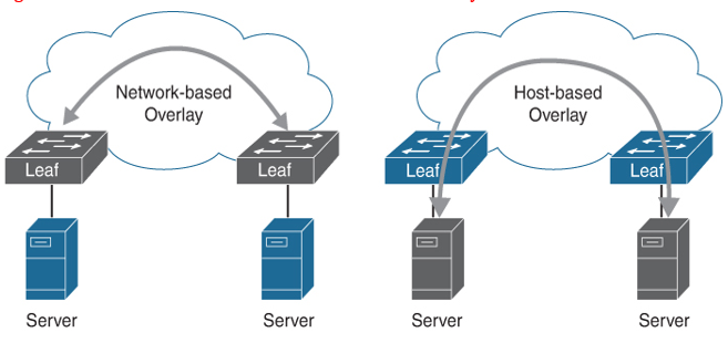
Figure 7-3 Network-Based vs. Host-Based Overlays
Overlay technologies allow the network to scale by focusing scaling on the network overlay edge devices. With overlays used at the fabric edge, the core devices are freed from the need to add end-host information to their forwarding tables. Most overlay technologies used in the data center allow virtual network IDs to uniquely scope and identify individual private networks. This scoping allows potential overlap in MAC and IP addresses between tenants. The overlay encapsulation also allows the underlying infrastructure address space to be administered separately from the tenant address space.