IGMP Snooping – Cisco Nexus Switch Routing
IGMP Snooping
The default behavior for a Layer 2 switch is to forward all multicast traffic to every port that belongs to the destination LAN on the switch. This behavior reduces the efficiency of the switch, whose purpose is to limit traffic to the ports that need to receive the data. IGMP snooping efficiently handles IP multicast in a Layer 2 environment; in other words, IGMP snooping makes Layer 2 switches IGMP-aware. IGMP snooping is used on subnets that include end users or receiver clients.
IGMP snooping is an IP multicast constraining mechanism that runs on a Layer 2 LAN switch. IGMP snooping requires the LAN switch to examine, or “snoop,” some Layer 3 information (IGMP join/leave messages) in the IGMP packets sent between the hosts and the router. When the switch hears the IGMP host report from a host for a particular multicast group, the switch adds the port number of the host to the associated multicast table entry. When the switch hears the IGMP leave group message from a host, the switch removes the table entry of the host. Because IGMP control messages are sent as multicast packets, they are indistinguishable from multicast data at Layer 2. A switch running IGMP snooping examines every multicast data packet to determine if it contains any pertinent IGMP control information.
IGMP snooping configured on Nexus switches examines Layer 2 IP multicast traffic within a VLAN to discover the ports where interested receivers reside. Using the port information, IGMP snooping can reduce bandwidth consumption in a multi-access LAN environment to avoid flooding the entire VLAN. IGMP snooping tracks which ports are attached to multicast-capable routers to help the routers forward IGMP membership reports. The IGMP snooping responds to topology change notifications. By default, IGMP snooping is enabled on the NX-OS device.
Figure 6-16 shows an IGMP snooping switch that sits between the host and the IGMP router. The IGMP snooping switch snoops the IGMP membership reports and the Leave messages and then forwards them only when necessary to the connected IGMP routers.
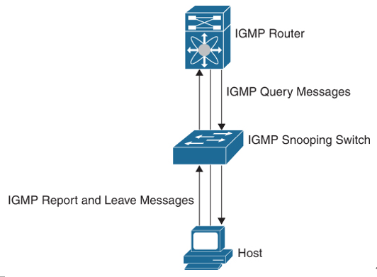
Figure 6-16 IGMP Snooping Switch
The IGMP snooping feature operates on IGMPv1, IGMPv2, and IGMPv3 control plane packets where Layer 3 control plane packets are intercepted and influence the Layer 2 forwarding behavior.
With IGMP snooping, the switch learns about connected receivers of a multicast group. The switch can use this information to forward corresponding multicast frames only to the interested receivers. The forwarding decision is based on the destination MAC address. The switch uses the IP-to-MAC address mapping to decide which frames go to which IP multicast receivers (or destination MAC).
The IANA owns a block of Ethernet MAC addresses that start with 01:00:5E in hexadecimal format. Half of this block is allocated for multicast addresses. The range from 0100.5e00.0000 through 0100.5e7f.ffff is the available range of Ethernet MAC addresses for IP multicast.
For IPv4, mapping of the IP multicast group address to a Layer 2 multicast address happens by taking the 23 low-order bits from the IPv4 address and adding them to the 01:00:5e prefix, as shown in Figure 6-17. By the standard, the upper 9 bits of the IP address are ignored, and any IP addresses that only differ in the value of these upper bits are mapped to the same Layer 2 address, since the lower 23 bits used are identical. For example, 239.255.0.1 is mapped to the MAC multicast group address 01:00:5e:7f:00:01. Up to 32 IP multicast group addresses can be mapped to the same Layer 2 address.
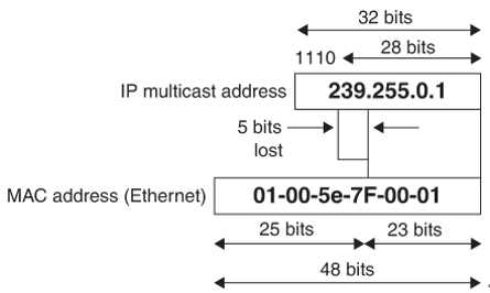
Figure 6-17 IP Multicast to Ethernet MAC Address Mapping
Because the upper 5 bits of the IP multicast address are dropped in this mapping, the resulting address is not unique. In fact, 32 different multicast group IDs map to the same Ethernet address, as shown in Figure 6-18. Network administrators should consider this fact when assigning IP multicast addresses. For example, 224.1.1.1 and 225.1.1.1 map to the same multicast MAC address on a Layer 2 switch. If one user subscribes to Group A (as designated by 224.1.1.1) and the other users subscribe to Group B (as designated by 225.1.1.1), they would both receive both A and B streams. This situation limits the effectiveness of this multicast deployment.
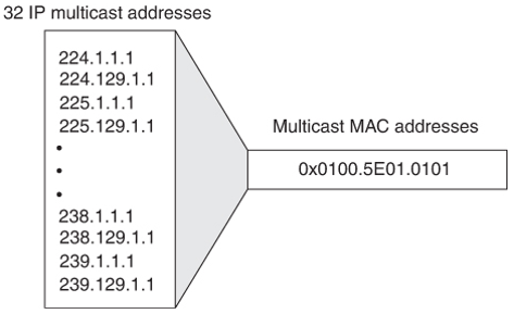
Figure 6-18 MAC Address Ambiguities