Cisco ACI Building Blocks – Cisco Describing Cisco ACI
Cisco ACI Building Blocks
Prior to Cisco ACI 4.1, the Cisco ACI fabric allowed only the use of a two-tier (spine-and-leaf switch) topology, in which each leaf switch is connected to every spine switch in the network with no interconnection between leaf switches or spine switches. Starting from Cisco ACI 4.1, the Cisco ACI fabric allows a multitier (three-tiers) fabric and the use of two tiers of leaf switches, which provides the capability for vertical expansion of the Cisco ACI fabric. This is useful to migrate a traditional three-tier architecture of core aggregation access that has been a common design model for many enterprise networks and is still required today. The primary reason for this is cable reach, where many hosts are located across floors or across buildings; however, due to the high pricing of fiber cables and the limitations of cable distances, it is not ideal in some situations to build a full-mesh two-tier fabric. In those cases, it is more efficient to build a spine-leaf-leaf topology and continue to benefit from the automation and visibility of Cisco ACI.
Figure 8-7 shows Cisco ACI two-tier and multitier topology.
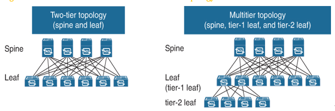
Figure 8-7 Cisco ACI Two-Tier and Multitier Topology
Leaf Switches
Leaf switches are the switches to which all endpoints (servers, storage, service nodes, and so on) connect. Leaf switches are available with various port speeds, ranging from 100Mbps to 400Gbps. Leaf switches are at the edge of the fabric and provide the VXLAN tunnel endpoint (VTEP) function. In Cisco ACI terminology, the IP address that represents the leaf VTEP is called the physical tunnel endpoint (PTEP). The leaf switches are responsible for routing or bridging tenant packets and for applying network policies.
In large-scale deployments, leaf switches are often dedicated and categorized by functions:
- Border leaf: Leaf switches that provide Layer 2 and Layer 3 connections to outside networks.
- Services leaf: Leaf switches that connect to Layer 4–7 service appliances such as load balancers and firewalls.
- Compute leaf: Leaf switches that connect to compute resources such as physical and virtualized servers.
- Storage leaf: Leaf switches that connect to storage devices for compute resources. This can include iSCSI, NFS, and other Ethernet medium storage devices.
Leaf switches do not need to be delegated to only one category. Depending on the design, the categories can overlap. For example, a leaf switch serving as a border leaf switch can also connect to compute resources.