Communication Between Hosts in Same VLAN/VNI – Cisco Network Virtualization
Communication Between Hosts in Same VLAN/VNI
An example of a VXLAN packet-forwarding flow between hosts in the same VLAN/VNI is shown in Figure 7-17.

Figure 7-17 Communication Between Hosts in Same VLAN/VNI
In Figure 7-17, Host-A and Host-B in VXLAN segment 5010 communicate with each other through the VXLAN tunnel between VTEP-1 and VTEP-2. This example assumes that address learning has been done on both sides and that corresponding MAC-to-VTEP mappings exist on both VTEPs.
When Host-A sends traffic to Host-B, it forms Ethernet frames with the MAC-B address of Host-B as the destination MAC address and sends them out to VTEP-1. VTEP-1, with a mapping of MAC-B to VTEP-2 in its mapping table, performs VXLAN encapsulation on the packets by adding VXLAN, UDP, and outer IP address headers to them. In the outer IP address header, the source IP address is the IP address of VTEP-1, and the destination IP address is the IP address of VTEP-2. VTEP-1 then performs an IP address lookup for the IP address of VTEP-2 to resolve the next hop in the transit network and subsequently uses the MAC address of the next-hop device to further encapsulate the packets in an Ethernet frame to send to the next-hop device.
The packets are routed toward VTEP-2 through the transport network based on their outer IP address header, which has the IP address of VTEP-2 as the destination address. After VTEP-2 receives the packets, it strips off the outer Ethernet, IP, UDP, and VXLAN headers and then forwards the packets to Host-B, based on the original destination MAC address in the Ethernet frame.
Communication Between Hosts in Different VLANs/VNIs
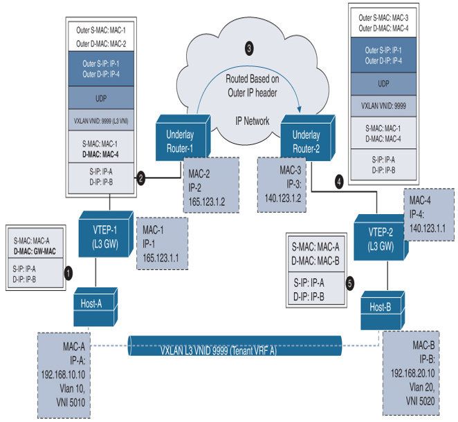
An example of a VXLAN packet-forwarding flow between hosts in different VLANs/VNIs is shown in Figure 7-18.

Figure 7-18 Communication Between Hosts in Different VLANs/VNIs
In Figure 7-18, Host-A belongs to VNI 5010 and Host-B belongs to VNI 5020, and both belong to the same tenant with VRF A. Since intra-VRF communication is allowed, Host-A can communicate with Host-B through the VXLAN tunnel in VRF A with L3 VNID 9999 between VTEP-1 and VTEP-2. Since the communication between Host-A and Host-B is inter-VLAN/VNI, L3 VNI will be used instead of L2 VNI during VXLAN encapsulation at the source VTEP. This example assumes that address learning has been done on both sides using the MP-BGP EVPN control plane and that corresponding IP-to-VTEP mappings exist on both VTEPs.
When Host-A sends traffic to Host-B, it forms Ethernet frames with an anycast default gateway MAC GW-MAC address of VTEP-1 as the destination MAC address and sends them out to VTEP-1. Since the destination MAC is the anycast gateway MAC, VTEP-1 does an L3 lookup and finds a mapping of IP-B to VTEP-2 in its routing table; it then performs VXLAN encapsulation on the packets by adding VXLAN, UDP, and outer IP address headers to them. This time, VTEP-1 uses Layer 3 VNI 9999 for the encapsulation since the communication is between hosts in different VLAN/VNI. In the outer IP address header, the source IP address is the IP address of VTEP-1, and the destination IP address is the IP address of VTEP-2. VTEP-1 then performs an IP address lookup for the IP address of VTEP-2 to resolve the next hop in the transit network and subsequently uses the MAC address of the next-hop device to further encapsulate the packets in an Ethernet frame to send to the next-hop device. Since the packet is routed, VTEP-1 will rewrite the source MAC to VTEP-1 and destination MAC to VTEP-2 in the inner Ethernet frame L2 header.
The packets are routed toward VTEP-2 through the transport network based on their outer IP address header, which has the IP address of VTEP-2 as the destination address. After VTEP-2 receives the packets, it strips off the outer Ethernet, IP, UDP, and VXLAN headers. VTEP-2 finds that the inner packet has a destination IP address of Host-B and does the routing lookup, rewrites the packet with the source MAC of VTEP-2 and destination MAC of Host-B, and then forwards the packets to Host-B.